Fiber optics for businesses: indoor, outside plant and how a link is certified
Single-mode or multimode, indoor, aerial or underground routes, loss budgets and OTDR traces: what lies behind a reliable fiber link and what you should receive at the end.
Between two buildings on the same site, between headquarters and a warehouse, or from the equipment room up to every floor: when distance or speed goes beyond what copper allows, the link is fiber. And it usually ends up in the hands of someone who did not install it, with no drawings and no idea how much margin is left.
Fiber rarely fails all at once. A link with little margin works for years, until a transceiver is swapped for a faster one, a patch cord is added or a connector gets dirty. That is when it turns out nobody measured the loss at installation.
Problems we solve
Undocumented links
Nobody knows how many fibers the cable has, which ones are in use or which way it runs.
Loss nobody measured
The link works with little margin until it is upgraded to 10 Gbps or a connector is added.
Poor splices
High loss or intermittent faults that show up with cold weather, moisture or a badly sealed closure.
Single-mode or multimode without clear criteria
Multimode between buildings that cannot reach the required speed, or mixed fiber types in the same link.
Dirty connectors
A particle on a 9 micron core adds loss and reflection. It is one of the most common causes of failure.
Third-party installs never certified
They are handed over with no reports or traces, and problems appear when there is no one left to hold accountable.
Single-mode or multimode: choosing the right one
The first decision for a link is the fiber type. Single-mode fiber has a 9 micron core and reaches kilometers; multimode has a 50 micron core and works with cheaper transceivers, but over hundreds of meters that shrink as speed goes up.
| OS2 single-mode | OM3 multimode | OM4 multimode | |
|---|---|---|---|
| Core | 9 µm | 50 µm | 50 µm |
| Typical wavelength | 1310 and 1550 nm | 850 nm | 850 nm |
| 1 Gbps | 1000BASE-LX: 5 km | 1000BASE-SX: 550 m | 1000BASE-SX: 550 m |
| 10 Gbps | 10GBASE-LR: 10 km · 10GBASE-ER: 40 km | 10GBASE-SR: 300 m | 10GBASE-SR: 400 m |
| 100 Gbps | 100GBASE-LR4: 10 km | 100GBASE-SR4: 70 m | 100GBASE-SR4: 100 m |
| Typical uses | Between buildings, sites and outside plant | Inside a building and in data centers | Inside a building and in data centers, with more reach |
| Usual jacket | Yellow | Aqua | Aqua or violet |
Reach per IEEE 802.3 for each interface; fiber types per ISO/IEC 11801 and ANSI/TIA-568.3-D. Longer-reach transceivers exist; the table uses the values in the standard.
Our general rule: between buildings or sites, single-mode. It covers any campus distance and the same cable supports future speeds by simply changing the transceivers. Inside a building or an equipment room, OM4 multimode can make sense on cost, as long as the distances fit the speed you will use in the coming years, not just today's.
Indoor and outside plant: what changes
Running fiber along a tray inside a building is not the same as hanging it from poles or pulling it through underground ducts. The cable, the hardware and the way of working all change.
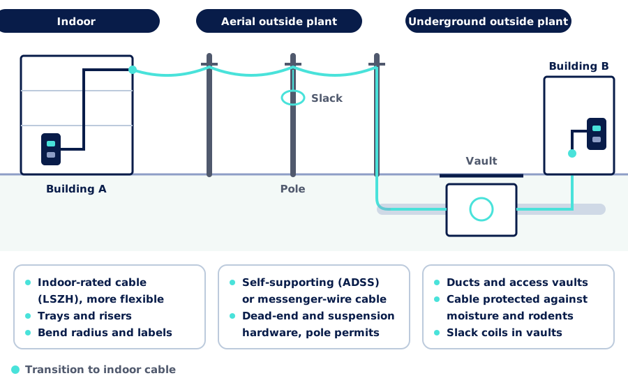
- Indoor. Indoor-rated cable with a low smoke, zero halogen (LSZH) jacket, along trays and risers, keeping the bend radius and with labels at each end.
- Aerial outside plant. Self-supporting (ADSS) or messenger-wire cable, dead-end and suspension hardware, and slack coils on the poles. Using poles requires permission from their owner.
- Underground outside plant. Ducts and access vaults, cable protected against moisture and rodents, and slack in the vaults for future repairs or branches.
- The transition. Outdoor cable is not made to stay inside the building: near the entry point it is spliced to an indoor-rated cable.
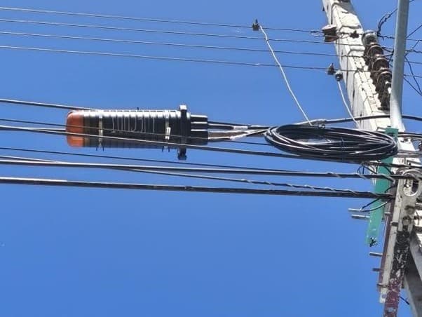
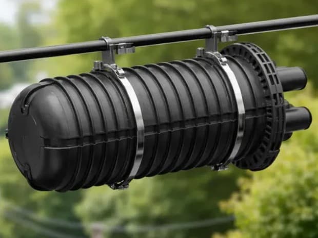
Splices and connectors: where the signal is lost
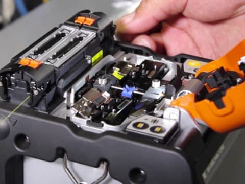
Fusion splicing
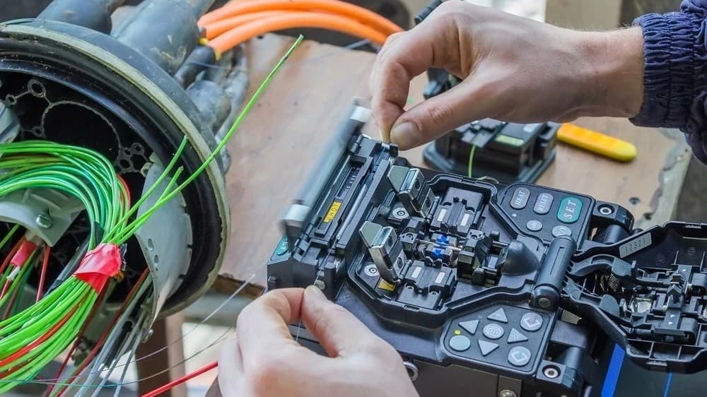
A fusion splicer aligns the cores of two fibers and fuses them with an electric arc. Done well, a fusion splice typically loses less than 0.1 dB and is protected in a tray inside the closure or the ODF. Connectors, on the other hand, can be unplugged and get dirty. That is why every connector is inspected under a microscope and cleaned before it is mated or tested.
How a fiber link is certified
Certifying a fiber link means measuring every fiber and comparing the result with what the design and the standard allow. It is done at two complementary levels:
Tier 1: total loss
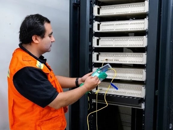
A light source at one end and a power meter at the other (OLTS). It measures the loss of every fiber at two wavelengths and compares it with the budget. It answers: does the link comply?
Tier 2: OTDR trace
A reflectometer sends light pulses and analyzes what comes back. It shows every connector, splice and bend with its location and loss. It answers: where is each loss?
The loss budget, with an example
Before measuring, you need to know how much loss is allowed. The budget adds up fiber attenuation, connector pairs and splices, using the maximum values in the ANSI/TIA-568.3-D standard.
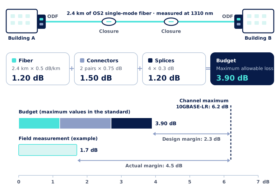
In this example link, 2.4 km long with two splice closures, the standard allows up to 3.90 dB at 1310 nm. The field measurement reads 1.7 dB, well below, and a 10GBASE-LR transceiver tolerates up to 6.2 dB of channel loss. That leaves 4.5 dB of actual margin for connectors that get dirty, future repairs or an extra patch cord.
In multimode the margin is much tighter: a 10GBASE-SR channel over OM4 allows only 2.9 dB at 400 m. There every connector counts, and one extra pair can leave the link with no margin.
The OTDR trace
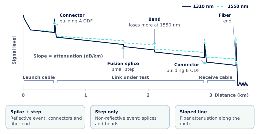
The trace reads from left to right: the slope shows fiber attenuation, spikes are connectors and the fiber end, and steps without a spike are splices or bends. To tell them apart, the link is tested at 1310 and 1550 nm: a bend loses much more at 1550 nm, a splice does not. Launch and receive cables make the first and last connectors visible, and testing from both ends gives the true loss of each splice.
Our process
We have carried out fiber optic installation, certification and documentation for telecommunications companies in different regions of Chile. We apply the same standard to business links:
- 1
Assessment and route survey
Route, pathways, available poles or ducts, building entries and equipment rooms.
- 2
Design
Fiber type, fiber count with room to grow, loss budget for every link and location of closures and ODFs.
- 3
Phased implementation
Indoor, aerial or underground runs with cable slack, fusion splices, tidy trays and distribution frames labeled fiber by fiber, coordinated with your operation.
- 4
Certification
Connector inspection, per-fiber loss at two wavelengths and OTDR traces.
- 5
Documentation
Reports, traces, a fiber schedule and route as-builts, ready for whoever manages the network.
- 6
Support
We remain available for expansions, new links and troubleshooting.
What you receive
Per-fiber loss report
At both wavelengths, compared with the budget for each link.
OTDR traces
In the OTDR's native format and as PDF, with every event and its distance.
Fiber schedule
Which fiber goes where, which ones are in use and which are spare.
Route as-built
Actual route, poles or vaults, closures and cable slack.
Labeling
Cables, closures, ODFs and ports identified with the same codes as the drawings.
Monitoring, if we operate your network
If we operate your network (network as a service or managed services), the link is integrated into our management system.
If you already have links installed by others and without reports, we can also test and document them and tell you how much margin they have left before an equipment change finds out for you.
Further reading
On AISCNET Learning, our technical training platform, you will find free articles and calculators on fiber:
- Optical Fiber Without Mystery: fiber types, decibels and loss budgets.
- Fiber Cable: Single-mode, Multimode & Jackets: OM/OS grades, construction and jackets.
- Fiber loss budget calculator: build the budget for your link.
- Maximum distance by fiber type: how far each speed goes.
- Received optical power: whether the signal arrives within the transceiver range.
For technical teams, we run the Fiber Optics for Installers course at AISCNET Learning for groups: splicing, connectorization and certification.
And on this blog:
- Cabling certification: what to require when a copper network is handed over.
- From a tangled rack to a telecom room that makes sense: where fiber links end.
- Site survey and design for tenders: how to specify a project before putting it out to tender.
If you need to connect two buildings or sites, or have undocumented links, the initial assessment is free: we discuss your case and send you a proposal. Write to us through our contact form or learn more about our network infrastructure service.
- Fibra óptica
- Monomodo
- Multimodo
- OTDR
- Presupuesto de pérdida
- Planta externa
- Empalme por fusión
- TIA-568.3